- #NUCLEO F446RE I2C PINS SERIAL#
- #NUCLEO F446RE I2C PINS PRO#
- #NUCLEO F446RE I2C PINS CODE#
- #NUCLEO F446RE I2C PINS PC#
#NUCLEO F446RE I2C PINS PRO#
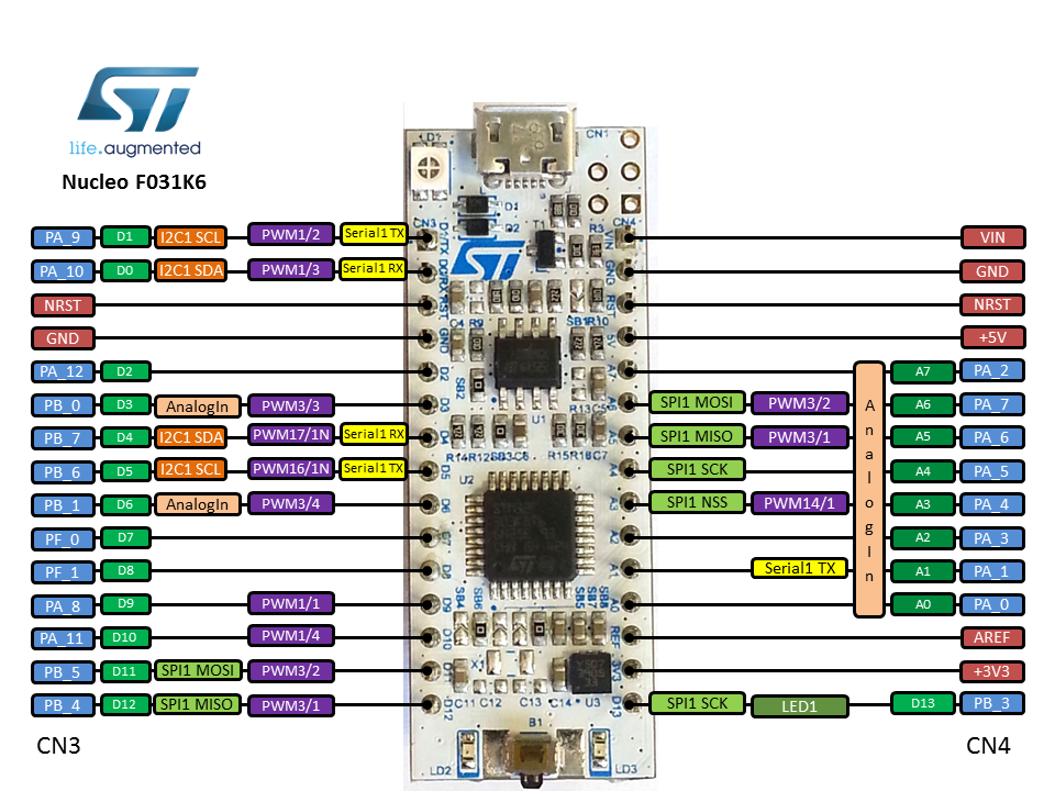
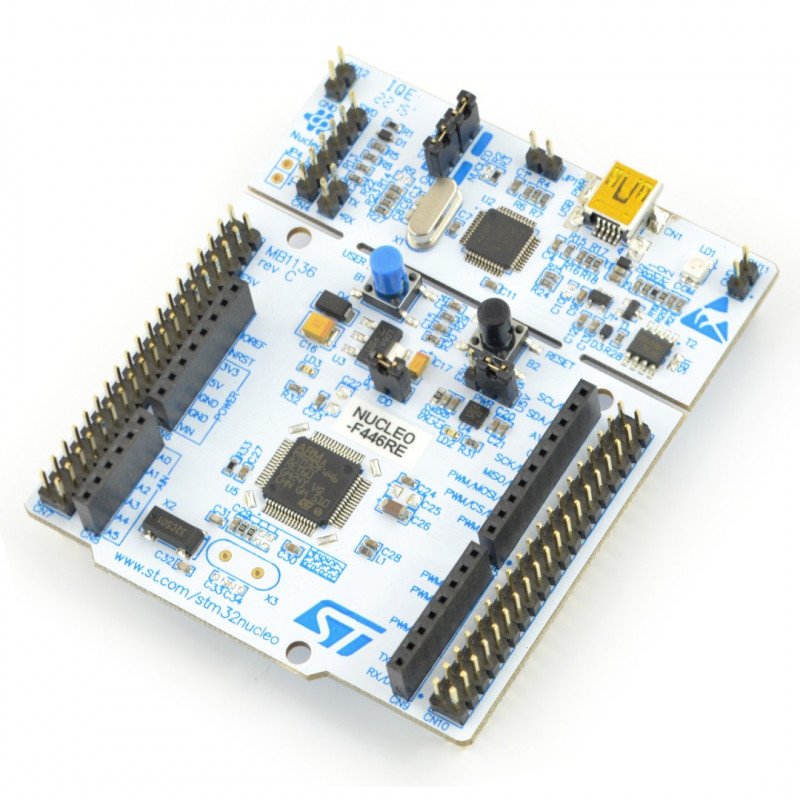
Note: More technical information can be found in the STM32 Nucleo-F401RE Datasheet, linked at the bottom of this page.Īrduino UNO, Arduino Pro Mini, Arduino Mega, Arduino Due, Arduino Leonardo, Raspberry Pi, PIC Development Board, AVR Development Board, MSP430 Launchpad, Intel Edison, ESP32 PC0, PC1, PC2, PC3, PC10, PC11, PC12, PC13, PC14, PC15Ĭan be used to power them module from battery They are also categorized with the table below: The name of the pins can be found in the image above. They comprise of GPIO pins, Analog Pins, Timer Pins, and Power pins. These pins are classified into CN7 and CN10 with each having 38 Pins.

These pins can also be used for I2C Communication A4 is SDA and A5 is SCLĬan be used to provide analog reference voltageĪcts as SCK, MISO, MOSI and CS pins respectively for SPI communicationĪcts as Rx and Tx pins respectively for USART communicationĪpart from the Arduino pins, the board also has 76 (38+38) GPIO pins as male headers on either side of the board as shown above. Provides 3.3V as output can also be used to power the MCU Each category pin can be tabulated as follows: The Arduino pins are split into category CN5, CN6, CN8, and CN9. The arduino like pins are female connector pins which exactly match the order and position of Arduino UNO pins and hence any Arduino shield can be used with these development boards. The pin one resembles the Arduino UNO and the blue one is the STM32 style ( Morpho). As you can see, there are two sets of pins.

The STM32 Nucleo board pinout is shown above. The Board operates with 3.3V supply but a wide voltage range of 7-12V can be provided to the VIN pin since it has an on-board voltage regulator. Similarly, there are two push buttons where one is user programmable, and the other is to reset the Microcontroller. This board also comes with an integrated ST-LINK/V2-1 programmer and debugger hence it is very easy to get started with this board.Īs shown in the image above, there are three LEDs, where LD1 is for indicating USB communication, LD2 is programmable LED, and LD3 indicates power. The Boards pinout is similar to Arduino UNO and has many other additional pins to expand performance. It features the ARM Cortex M4 32-bit STM32F401RET6 microcontroller which is in LQFP64 package. Stay tuned for the upcoming tutorials and don’t forget to SHARE these tutorials.The STM32 Nucleo boards are the official Development Boards from STMicroelectronics. And this is what happened exactly as you can see on the terminal screen.ĭid you find this helpful? If yes, please consider supporting this workand sharing these tutorials! Which we’ll be doing in the future in another tutorial.īut anyway, we should now expect to see another device at the 0x27 address as well as the MPU6050 at 0圆8. This module has an I2C slave address of 0x27 as a default address if no solder bridge is touched! You can still play around with those bridges to change the device address to allow many I2C_LCD devices on the same bus. In the second test, I’ve just added another I2C module to the bus lines which is the I2C_LCD interface IO expander (PCF8574T).
#NUCLEO F446RE I2C PINS SERIAL#
Anyway, we should expect to see that address after running the example on the “Tera Term” serial terminal on my PC. We can change only one bit of that address so there could be 2 MPU6050 sensors on the same bus at maximum. The I2C address for this slave device is 0圆8 as stated in the datasheet.
#NUCLEO F446RE I2C PINS CODE#
Those are the CubeMX configurations I’ve used for UART1 & I2C1 peripherals I2C Scanner Project Code Listingĭownload STM32 I2C Scanner Project Folder Test #1 Setup & Resultsįor the first test, I’ve connected an MPU6050 IMU sensor to the SCL & SDA lines of I2C1 as you can see in the image down below.

#NUCLEO F446RE I2C PINS PC#
The UART will be used to send the address readings to the PC (with USB-TTL), and the I2C master will do the address scanning as we’ll see next. Then, it can be handy to run this example and make sure everything is OK.įor this example project, you’ll need to configure one UART peripheral and one I2C interface in master mode. Maybe the device you’re trying to communicate with is actually damaged and no longer works. It can also tell if an I2C device is actually working or not. Just run this example and get the addresses. That can be useful if you don’t know the address of any I2C device or just not sure about it. The I2C Scanner example is a very common Arduino sketch example to scan the I2C bus for available devices and get their addresses (if found). To check for the connected slave devices on the I2C bus and report their addresses over UART to our PC. In this short tutorial, we’ll be creating an STM32 I2C Scanner example project. Previous Tutorial Tutorial 45 Next Tutorial STM32 I2C Scanner Example STM32 Course Home Page 🏠


 0 kommentar(er)
